| Posting to help anyone else trying to fix their IL60 plate amp. While I will admit this basically just follows what the service manual says, here were my steps: Power Board: 1. Replace the two IRF740 mosfets. I also went ahead and replaced the 22 ohm resistors and the 422 ohm resistors. On one amp I also had to replace the in5242b diodes. Replace the IRF640 mosfets. Visually check the rest of the board for damages components and replace as necessary. 2. Test the power board as described in the service manual and verify an output of ~18-19v. Linear Board (Output board) 3.First, screw both bias pots closed (counter clockwise). 4. Remove the linear board and test each mosfet for shorts. If any have a short, replace all four. (2 x IRF9540 and 2 x IRF640). For the IRF9540, the part is obsolete, but I found some "Bojack" brand ones on Amazon. I do not recommend mosfets from unverified sources, but they are working for me. Your mileage may vary. Testing 5. Be sure to use some thermal compound when you put the boards back together and use the transistor insulators where they were at disassembly. 6. Follow the bias procedure. I had 0.0mV when the pots were both counter clockwise. You will see that they are very sensitive, so "eyeballing" this doesn't work. If you are biased to high, you will blow the new transistors and have to start over (ask me how I know!). Good luck! |
|
| qwertdyukg | |
| So I replaced the R509 and the green light came back on and the unit started working again. Great! But now the same board gets super hot just from turning it on, I turn it off after it reaches 125F. Takes it about 3min to get this hot. Any ideas? | |
| I was hoping I could get some advice on how to remove the back panels on my Infinity Interlude IL60's. I removed all the edge screws but the panel still is pretty tight in there. I'm afraid to get a flat blade in between to pry them open as I might be missing something. Has anyone removed the rear panels on their Infinity IL series towers? | |
| If it's hard for you to find <a href=guidesfordigitaltransformation.com> Digital Transformation comparison </a> sites, then maybe I can help. | |
| Thank you for all of the posts on the bad resistors. I have one bad sub and I am hoping that is the fix for it. I also have 5 broken toggles on the rear panel from someone transporting the speakers on their backs. These are the smaller toggles. According to the manual, they are in locations S1, S3, and S4 (Infinity part # SR0007). My question is, does anyone know what the non-infinity replacement part for this and where can I find it? Can you post a link to the part? |
|
| Here's the parts that I used: [url=R509 100K Ohm 1W resistor[/url] - got an set on Amazon. I probably should have bought a kit or a set of resistors, but I only needed the 100K 1W for this project. Q501 and Q502 - IRF740 - got four of these (two to spare for other speaker if needed in future) Q504 and Q507 - IRF640 - got four of these as well. HC1011 - call Infinity Parts at (877) 871-6755. I also found one on aliexpress.com, shipping from China. So I'd recommend Infinity parts first. |
|
For some reason it won't let me edit my post above, so here the pics that were supposed to be embedded inline 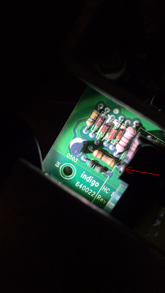 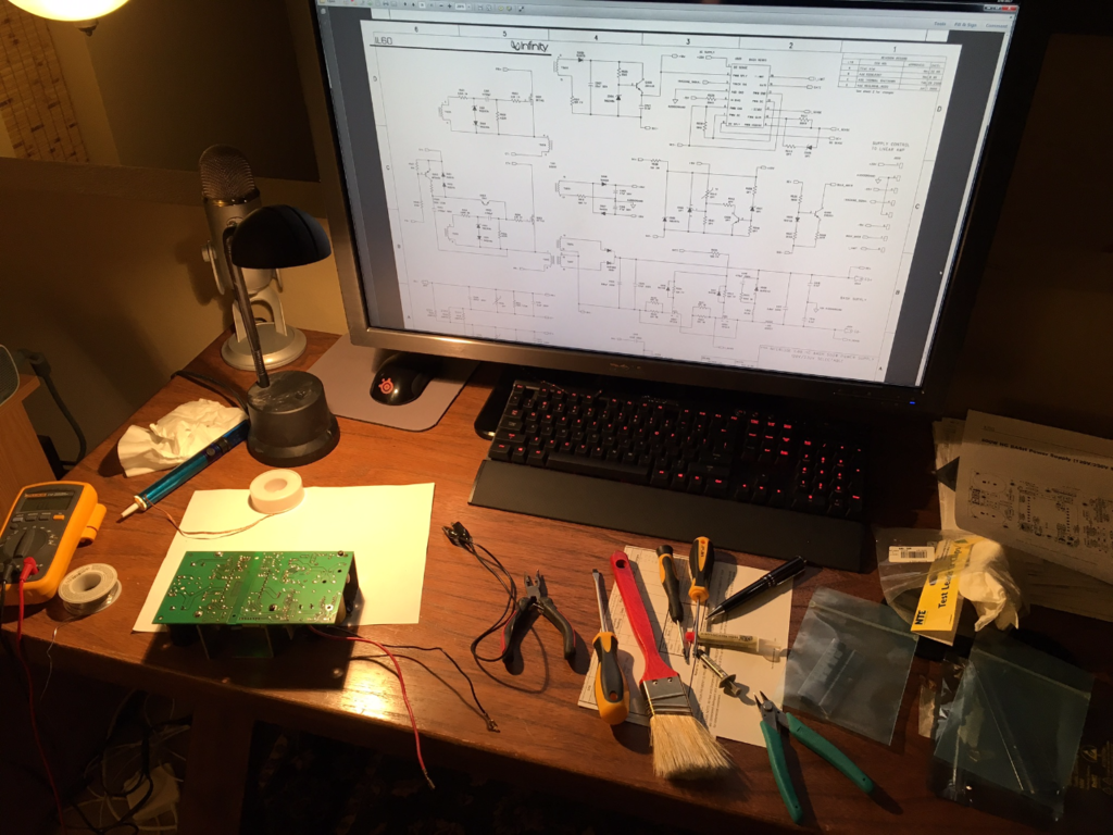 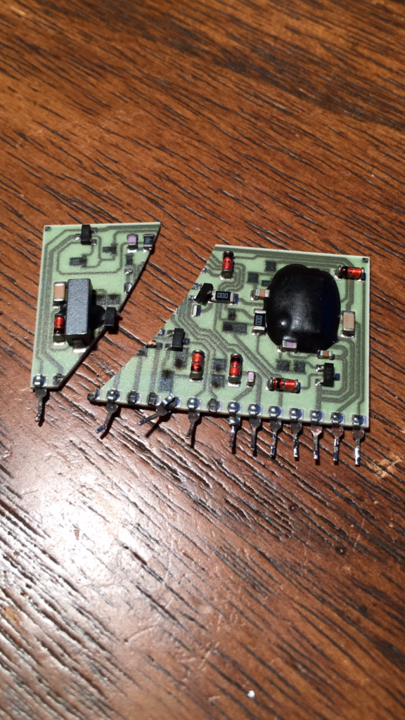 |
|
| Thanks all for the amazing information on this thread - I was able to resurrect my beloved IL-60 sub-woofer on the left hand speaker. It's almost 10 years ago that the first post was made, so I'm glad it's still alive on the internet! I had an unusual problem - the light on the front volume control worked OK (red on standby, green when a signal detected), however there was no sound output from the sub. After pulling the speaker apart, I found this thread and immediately noticed that my R509 was a little dark, in fact the yellow band was almost gone. It measured 120K, so no too far off, but it got replaced anyway: [img] However this didn't fix the problem, so I started troubleshooting using one of the bulletins in the service manual (Service Bulletin INF2001-04 Rev2 May 2005). I didn't quite like the resistance measurements I was seeing fo I changed all the MOSFETs (Q501, Q502 are IRF740, and Q504/507 are IRF640) - I ordered replacements from digikey.com, after which they measured just right. The circuit has capacitors on it, so measurement takes a couple of seconds to stabilize. [img] But it still didn't work... Aaargh, so I had to pull up the circuit diagram and follow it carefully with a multi-meter. I noticed that while Q504/507 were getting plenty of input power, they were never turning on. The service bulletin says that there should be about 10-20V nominal power on the CD+- rails (that connects to the amplifier plate). The part that drives this circuit is the BASH hybrid IC: HC1011. I took a close look using a flashlight, and what do you know - a hairline crack on the board?! I wonder if this is common, or if mine just had a defect? [img] I probably could have fixed it using some superglue and carefully re-soldering the broken tracks, but I was able to find a replacement by calling Infinity/Harman. Here's the details from the live chat session: The part that you need is still available in our warehouse. Yo can call us to this number (877) 871-6755 to place your order. because we cannot process an order through chat. Price, including shipping: $32.34 So I ordered one by calling this number - I asked them for part HC1011 and they found it right away. I also found on by searching google shopping on aliexpress.com, was $40 from China, so if you're in the USA the best bet is direct from Infinity/Harman. After replacing it, I now get 18V on the CD+- power rails, just like I was supposed to. I also ran through the steps for re-biasing the output MOSFETS (see IL60 ADJUST BIAS PROCEDURE in the service manual), I marked the positions of R11 & R27 with a sharpie before turning them counter clockwise, they were almost exactly right so this step was probably not necessary. Powered it all up, but still no bass. But now I'm getting a proper signal output on the speaker lines (which wasn't there before). If you put the multi-meter into AC Volts, should see movement every time a bass drum is hit Thanks again to all the posters for the great info in this thread![/img] |
|
| So in my attempt to fix, when removing the damaged R509 resistor, I guess I pulled out the solder pad on one of the holes (the hole closest to Q503). Now solder will not stick when soldering a new resistor back in. After doing some research, folks fix this using a few techniques, from soldering to the next available spot, or to the trace, or using a jumper. Can anyone recommend which repair method might be best in this case? | |