| View previous topic :: View next topic |
| Author |
Message |
fpc3
Joined: 02 Feb 2009
Posts: 31
Location: Shawnee, Kansas
|
 Posted: Wed Feb 04, 2009 3:03 pm Post subject: Posted: Wed Feb 04, 2009 3:03 pm Post subject: |
 |
|
I soldered a strap across the power relay contacts. When the power switch is turned on, the standby light now flashes. No sound and no display, and no reaction to remote. Don't know how to get it out of standby.
I assume it needs the voltages produced by the SMPS to function. There appears to be nothing usable on the smps connector.
I do read various DC voltages on the main board now. I only connected the right front speaker (I assume that would be good for a test).
It would seem the next step is to replace the KA1M0380R on the smps board.
Thanks!
Frank
 |
|
| Back to top |
|
 |
vtech
Joined: 08 May 2006
Posts: 1264
Location: USA
|
| Posted: Wed Feb 04, 2009 6:25 pm Post subject: |
|
|
Completely forgot about the rest of the SMPS; (CN4 which goes to CN205 and indeed provides extra DC levels needed)
and yes, jumping RY201 is not going to provide any of them.
Bottom line, SMPS has to be fully operating as you have indicated. |
|
| Back to top |
|
|
fpc3
Joined: 02 Feb 2009
Posts: 31
Location: Shawnee, Kansas
|
| Posted: Wed Feb 04, 2009 10:01 pm Post subject: |
|
|
vtech,
I was thinking I might try to jumper voltages from the main power supply back to the other voltage points formerly served by the SMPS. Several of them are the same. I might be able to get most (all?) of them that way. Assuming the additional current can be handled, the only thing lost would be the ability to turn the unit on from standby with the remote. Wouldn't you think everything else would work?
If it worked, I could then feel more comfortable with spending $20 to buy the IC and having to wait a month. I also found the IC at London and Germany. But, euros are involved, etc. Those suppliers just didn't seem to be set up to deal with an international sale. I understand what you meant when you said you "couldn't find it anywhere".
Find that SMPS diagram you slaved over for days. 
Thanks!
Frank |
|
| Back to top |
|
|
fpc3
Joined: 02 Feb 2009
Posts: 31
Location: Shawnee, Kansas
|
| Posted: Wed Feb 04, 2009 10:24 pm Post subject: |
|
|
Do you know why the suffixes such as VA, VS, and VM are used for some of the voltages out of the SMPS?
e.g.: +5VA, +5.5VS, +12VM
Is it possible that those voltages do not use chassis ground... Instead they use an isolated ground? I notice there are DGnd, MGnd, and AGnd.
That would make it a little difficult to use power from the main power supply.
Thanks!
Frank |
|
| Back to top |
|
|
jts1957
Joined: 24 Nov 2008
Posts: 2476
Location: Far, Far Away
|
| Posted: Wed Feb 04, 2009 10:28 pm Post subject: |
|
|
If you have enough variable external power supplies you could probably "prove" all else is O.K.
If you combined, let's say (for testing purposes ONLY) the 12 volt supplies, the 5 & 5.5 together and combine the 2.5 & 3.5 and compromise to say 3 volts, you still would need at least four supplies. Plus 5 - Minus 5 - 12 volt - 3 volt.
If external supplies can provide say up to 1 amp and if you don't try operating everything at once, with all speakers connected, at full volume, for a limited time, etc., that should be enough to satisfy you.
Not sure if display AC would be there or not. |
|
| Back to top |
|
|
jts1957
Joined: 24 Nov 2008
Posts: 2476
Location: Far, Far Away
|
| Posted: Wed Feb 04, 2009 10:30 pm Post subject: |
|
|
Possibly A= all time (Maybe analog)
S= switched
D= delayed (or digital) |
|
| Back to top |
|
|
fpc3
Joined: 02 Feb 2009
Posts: 31
Location: Shawnee, Kansas
|
| Posted: Thu Feb 05, 2009 12:10 am Post subject: |
|
|
Thanks JTS,
Yes I agree... If I can come up with several supplies like you say, I could wire them in there even if some of them did have isolated grounds. I guess I'll get started on that.
It's unfortunate that Kenwood didn't make a schematic of that board.
Thanks for the help with the suffixes too.
Frank |
|
| Back to top |
|
|
vtech
Joined: 08 May 2006
Posts: 1264
Location: USA
|
| Posted: Thu Feb 05, 2009 4:01 am Post subject: |
|
|
| fpc3 wrote: |
Do you know why the suffixes such as VA, VS, and VM are used for some of the voltages out of the SMPS?
e.g.: +5VA, +5.5VS, +12VM
Is it possible that those voltages do not use chassis ground... Instead they use an isolated ground? I notice there are DGnd, MGnd, and AGnd.
That would make it a little difficult to use power from the main power supply.
Thanks!
Frank |
You can sub the rest of the supplies if you want & unfortunately I no longer have the diagram for the SMPS. To answer your question;
A denotes Audio, S denotes standby and M stand for motor. Strictly used as a means to indicate what part of the circuit it is mainly used.
As far as the ground reference, your motor, digital and audio grounds in this application are all the same & connected to chassis ground. (verify it with a meter). Any ground isolation is probably some of the Audio outs or optical in/outs?
Either way, if you are going to go the sub route, make sure not to mix them up as you can inadvertently damage something.
Also, just thought of something else you should check. While it has nothing to do with the power issue, it is a rather idiotic design issue that caused major problems with the unit mainly in the DSP circuit;
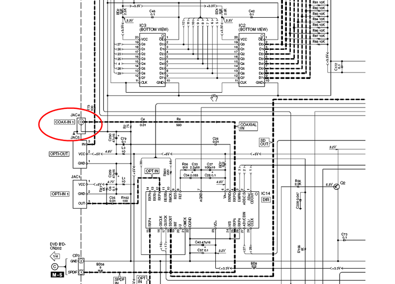
As a precaution, make sure to check the ground lug solder connection on the coax-in jack on the DSP board.(along with the screw that connects it to the back panel). For whatever reason, that is the only ground connection for the DSP circuit and if cracked, it can easily ruin several IC's on that board due to floating ground.
 |
|
| Back to top |
|
|
fpc3
Joined: 02 Feb 2009
Posts: 31
Location: Shawnee, Kansas
|
| Posted: Thu Feb 05, 2009 5:12 am Post subject: |
|
|
thanks vtech for the tip on the screw and ground lug. Interestingly, I had removed the mainboard to remove and check the caps that I suspected were leaking (they were fine). When I put it back in yesterday, I put just a couple of screws in the back to hold things back together. The screw you reference happens to be one I did put back. I did that just because it was near the center of the back panel and it served to hold things. (lucky!)
I just now put all the screws back in. I am hoping that there weren't other situations like the one you covered. Why in the world??
Thanks for the explanation on the suffixes. I have been reading the schematics, and like you say, all grounds appear to be common.
I decided the easiest way to bypass the power is to remove the smps board and skin back each wire a little bit and in a staggered pattern in the cable that connects to the smps board. I will then solder wires to each of those wires. I can then restore the cable when necessary and I won't have to worry about feeding voltage back into the smps board. I will then find as many voltage sources as I can on the main board to solder the other end of the wires. I think it has a chance of working as long as I don't exceed the current capabilities of the supplies. I figure I'll measure the voltage at those points before and after each connection. If the voltage drops too much, I'll use an external supply.
What do you think?
Thanks for the support.
Frank |
|
| Back to top |
|
|
fpc3
Joined: 02 Feb 2009
Posts: 31
Location: Shawnee, Kansas
|
| Posted: Fri Feb 06, 2009 2:04 am Post subject: |
|
|
Well folks, I think we are close to the end of an economical repair of this thing. I have power on all the leads now from internal and external supplies and I can't get it out of standby. Some of the voltage levels I am providing aren't exact. And I have all the grounds going to a common point. Perhaps there is something critical there that isn't as exact as it needs to be. Not sure. But still no display or any action from device.
Thanks!
Frank |
|
| Back to top |
|
|
|
|
|
|
You can post new topics in this forum
You can reply to topics in this forum
You cannot edit your posts in this forum
You cannot delete your posts in this forum
You cannot vote in polls in this forum
|
eServiceInfo on FB -
Service Manuals Free Download -
Service Diagrams
Free TV Schematics Download -
Pinout Master -
Jabse Service Manual Search -
Jabse.InK -
onTap.bg
Poblizo.com : ïúòåøåñòâèÿ -
Top free service manuals download resources 2026
Latest Service Manuals :
[smd] RVW Series SINDECON • 6710 (b+s) 6715 (b+s) HP • LG+CM9740+sm LG • pg-c30xe-sm Sharp • mch6611 Sanyo • 22RH591 SB 1355305890 Philips • 2sc5513 . Electronic Components Datashee • 1490 ELBE • Lg tv CI-25H40 LG • SGH-T100 service manual Samsung •
|

