| View previous topic :: View next topic |
| Author |
Message |
Guest
|
 Posted: Mon Dec 01, 2008 8:44 pm Post subject: Vintage Pioneer Amplier SA-500 Repair HELP!!! Posted: Mon Dec 01, 2008 8:44 pm Post subject: Vintage Pioneer Amplier SA-500 Repair HELP!!! |
 |
|
| I have a vintage SA-500 pioneer amplifier that was not outputting anything out of the left channel. I opened it up and saw the fuse was blown for the left channel. i replaced the fuse, switched it on, and it blew immediately. After this, I de-soldered 1 of the two IC transistors. When I replaced the fuse, the amp worked with audio in both channels, even though I didn't replace the transistor.. I only removed it. So I was convinced the transistor was internally shorted out. I ordered a new set of replacements, soldered them in.. turned on the amp and the fuse for the left channel blew immediately again, and the solder point near the transistor I replaced was smoking a bit. And.. I'm back to where I started. Any idea what's up here? Sorry for the long-winded question. Thanks! |
|
| Back to top |
|
 |
joshg3p0
Joined: 01 Dec 2008
Posts: 3
|
| Posted: Mon Dec 01, 2008 8:45 pm Post subject: |
|
|
I forgot to log in.. I'm a registered user. In case anyone cares.  |
|
| Back to top |
|
|
kenray
Guest
|
| Posted: Mon Dec 01, 2008 9:55 pm Post subject: |
|
|
| if you have a multimeter i would suggest you check any other transistors around the one you replaced for shorts |
|
| Back to top |
|
|
joshg3p0
Joined: 01 Dec 2008
Posts: 3
|
| Posted: Mon Dec 01, 2008 9:59 pm Post subject: |
|
|
| I can test the other transistors for short. I think I did that, but I'll try again. There are 2 transistors per channel. I replaced both in the left channel, and experienced the blown fuse problem. Would anything else nearby affect that part of the circuit? |
|
| Back to top |
|
|
vtech
Joined: 08 May 2006
Posts: 1264
Location: USA
|
| Posted: Tue Dec 02, 2008 3:27 am Post subject: |
|
|
| joshg3p0 wrote: | | I can test the other transistors for short. I think I did that, but I'll try again. There are 2 transistors per channel. I replaced both in the left channel, and experienced the blown fuse problem. Would anything else nearby affect that part of the circuit? |
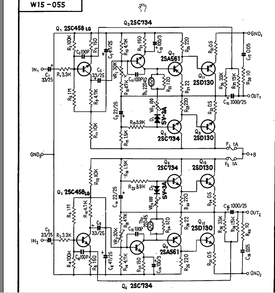
There is a lot more than just two transistors( they are not IC's btw). What you are looking at is the old style output transistor(s) mounted on heatsinks leading you to believe they are the only thing there...
When/if the outputs are shorted, generally other devices will be taken out at the same time and there is no rule as to what will or won't be gone at the same time? Unless you are experienced, you need to test any other semiconductor & low ohm resistor(s) or else you will likely blow the new outputs as soon as the set is powered back up.
In looking at the schematic and from what I can see, you may have several other resistors/transistors that are probably bad. especially the low-value resistors--(btw, your new transistors are more than likely bad already). I also see the infamous SV3 bias diode that was used extensively on a lot of the older amps and known to be troublesome. Since you still have a good channel, you can use it as a reference for measuring suspect device (s)
 |
|
| Back to top |
|
|
joshg3p0
Joined: 01 Dec 2008
Posts: 3
|
| Posted: Tue Dec 02, 2008 3:54 am Post subject: |
|
|
| Thanks. I'll take a closer look at that schematic and try testing the components and compare them to the good channel as a reference. Any other advice. So far this has been helpful. |
|
| Back to top |
|
|
vtech
Joined: 08 May 2006
Posts: 1264
Location: USA
|
| Posted: Tue Dec 02, 2008 4:06 am Post subject: |
|
|
May not be a bad idea to change or at least test the electrolytic capacitors(if you have a tester?). The amp at this age will probably need them---After you have found and corrected the problem.
Generally they do not cause a short or a catastrophic problem, just dry out(value lowers, ESR goes up) or visually leak out after years of use. |
|
| Back to top |
|
|
torbjorn
Joined: 07 Jun 2007
Posts: 370
Location: Sweden
|
| Posted: Tue Dec 02, 2008 9:22 am Post subject: |
|
|
When troubleshooting an amplifier with a such problem, it is a good idea to replace the fuses by suitable current limiting resistors during testing. Then, if anything goes wrong, there is no risk of a temporary current surge that may cause unnecessary damage.
Don't forget to adjust the bias (VR3) and DC balance (VR1) after repair. Probably, you will find instructions for that in the service manual.
A common fault on old Pioneer amps was that the power transistors got shorted to the heat sink due to nicks or burrs cutting through the mica insulators. |
|
| Back to top |
|
|
|
|
|

