| View previous topic :: View next topic |
| Author |
Message |
fpc3
Joined: 02 Feb 2009
Posts: 31
Location: Shawnee, Kansas
|
 Posted: Mon Feb 02, 2009 10:58 pm Post subject: Kenwood DVR-505 will not power up Posted: Mon Feb 02, 2009 10:58 pm Post subject: Kenwood DVR-505 will not power up |
 |
|
A circuit in a Kenwood DVR-505 is preventing an inline relay from picking up, which, if operating correctly would supply 110 VAC to the primary power transformer.
DVR-505 is a DVD player & AV Receiver.
Does anyone know what conditions are sensed that would disallow the relay from picking up?
The red LED indicators flash. No display. Nothing appears burnt. fuses good. Thinking about bypassing relay contacts for a test, but looking for advice first.
Thank you!
Frank
Last edited by fpc3 on Thu Feb 05, 2009 12:11 am; edited 3 times in total |
|
| Back to top |
|
 |
jts1957
Joined: 24 Nov 2008
Posts: 2476
Location: Far, Far Away
|
| Posted: Tue Feb 03, 2009 12:18 am Post subject: |
|
|
| Disconnect everything except power cord - Does it still fail? |
|
| Back to top |
|
|
fpc3
Joined: 02 Feb 2009
Posts: 31
Location: Shawnee, Kansas
|
| Posted: Tue Feb 03, 2009 3:31 am Post subject: |
|
|
Yes. With all inputs, outputs, and speakers disconnected, the 5 LEDs flash, and there is no display, the relay doesn't pickup, and no power is applied to the primary of the transformer.
I did do the "reset", which had no effect.
Are you indicating that the condition I describe would occur if there was a shorted speaker connection (?).
As information, the unit worked fine one day, and after not being used for a week, it started this. It seems a surge could have occurred during power off (??)
Thanks for the help!
Frank |
|
| Back to top |
|
|
vtech
Joined: 08 May 2006
Posts: 1264
Location: USA
|
| Posted: Tue Feb 03, 2009 5:51 am Post subject: |
|
|
...Used to see them often.... One of the few models that used a different brand subwoofer! (made by Boston Acoustics).... & not too friendly for repair especially if you had to pull the main board or follow their schematic...etc.
The firm I used to work for, sold the package for some time( was actually a good seller!) and I was one of unlucky ones who had to fix them.
Regarding the power problem, do you have the standby from power supply?
If you are sure of the protection causing the problem, it is likely the outputs?
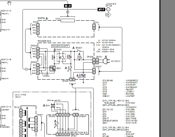
Whether your's have the same problem or not, Power supply was a common failure with those units. Most of the time were either caps or the main primary chopper IC.(when hit by a small surge). Of course, there was no diagram for the SMPS & the IC not available and you would have to change it as a module( it was not worth doing anymore circa 07). Not sure if it's even available anymore?
here's a diagram of the relay
 |
|
| Back to top |
|
|
fpc3
Joined: 02 Feb 2009
Posts: 31
Location: Shawnee, Kansas
|
| Posted: Tue Feb 03, 2009 3:29 pm Post subject: |
|
|
Thanks for the information and advice...
I have seen the Standby red LED over the power switch flash but I don't know how to initiate that. Now, with the power supply on, just the 5 mode LEDs flash. I can't seem to get any of those indications to change now.
I am not sure it is the protection circuit, although the relay isn't picked up and I just assumed that was the place to start.
Can having an open speaker circuit could cause this? Or, insofar as the output circuitry is concerned, is it just a shorted speaker circuit or shorted PA that could cause the protection circuit to do this?
I just noticed that there is some transparent gray substance on the PCB under the two large 4700 mf @ 50v filter caps. I had assumed that was glue, but now, after your comment about power supply problems, maybe it is leakage from the caps! What do you think? Does the primary relay pick up for a just an instant ... long enough to sense for an excessive load?
Thanks again!
Frank |
|
| Back to top |
|
|
fpc3
Joined: 02 Feb 2009
Posts: 31
Location: Shawnee, Kansas
|
| Posted: Tue Feb 03, 2009 4:25 pm Post subject: |
|
|
| I just removed the mainboard and removed the filter caps. The "substance" on them is glue. It is just on the outside of the caps and the caps test good. (darn) |
|
| Back to top |
|
|
jts1957
Joined: 24 Nov 2008
Posts: 2476
Location: Far, Far Away
|
| Posted: Tue Feb 03, 2009 7:31 pm Post subject: |
|
|
| What is the voltage at CN204 pin # 2? Also at pin # 3 (at standby and at power on attempt)? |
|
| Back to top |
|
|
fpc3
Joined: 02 Feb 2009
Posts: 31
Location: Shawnee, Kansas
|
| Posted: Tue Feb 03, 2009 9:29 pm Post subject: |
|
|
jts,
Thanks to vtech's schematic, I was able to read voltages as follows:
CN204
pin 1 gnd
pin 2 pulsing dc from 0v to +11v peak @ ~ 2 Hz
pin 3 0.00 vdc
pin 4 pulsing dc from 0v to +11v peak. The voltage on this pin constantly pulses from 0v to +1.5v peak. And is then pulsed, perhaps twice a second to 11v.
(this is the red wire in the corner of the pcb that ties to pin 1 of CN205, which is also red.)
Thanks for the help and your time with this,
Frank |
|
| Back to top |
|
|
fpc3
Joined: 02 Feb 2009
Posts: 31
Location: Shawnee, Kansas
|
| Posted: Tue Feb 03, 2009 9:31 pm Post subject: |
|
|
The above voltages are taken with power "on". With power off, voltages are all 0.00. I cannot get it into standby mode.
The remote control has no effect with unit on or off. |
|
| Back to top |
|
|
jts1957
Joined: 24 Nov 2008
Posts: 2476
Location: Far, Far Away
|
| Posted: Tue Feb 03, 2009 9:46 pm Post subject: |
|
|
Looks like SMPS is defective. I assume from schematic that 5.6Volt is a standby source and should be present at ALL times.
Do you have a DC power supply? You could substitute your own 5.6 volts on that line and see what happens. |
|
| Back to top |
|
|
|
|
|
|
You can post new topics in this forum
You can reply to topics in this forum
You cannot edit your posts in this forum
You cannot delete your posts in this forum
You cannot vote in polls in this forum
|
eServiceInfo on FB -
Service Manuals Free Download -
Service Diagrams
Free TV Schematics Download -
HARDW.net -
Pinout Master -
Jabse Service Manual Search -
Jabse.InK -
onTap.bg
SnimkiOt.com -
Poblizo.com : ïúòåøåñòâèÿ
Latest Service Manuals :
KA5Q SERIES FAIRCHILD • 22rh781 Philips • 2sc5075 Toshiba • hfe lafayette la-25 en Lafayette • ml 320, 321 oki • 20LCD MCU BEKO • Allocchio Bacchini 411 ALLOCCHIO BACCHIN • hfe pioneer vsx-5500s 5400 service Pione • Statement.mesa Sep78 xerox • KM-C2520 C3225 C3232 3050 4050 5050-IG-D •
|

