| ...Oh well , chalk it up to experience. These things are really not meant to be easily repaired & can be a reall PITA . Sadly in today's consumer electronic market "disposable" is the name of the game. |
|
| In the end I gave in and soldered the contacts together. Took me two hours to put the thing back together, and it's still not working. I must have fried the IC when I applied inverted polarity.
Thanks a lot for your help, I wouldn't have known where to even start without you. Sadly, no good results... If you have some other idea about anything I could do to repair it I'd be happy to know it... otherwise I'm through with this thing. Typical of sony: make a beautiful piece of gear and then apply abundant stupidity and proprietary everything. Would it have killed them to add a simple reverse voltage protection, as everybody else does? Maybe even use a *gasp* standard, universally compatible barrel plug? I'm not trying to blame them for my mistake; I should have been more careful with the external pack. But had I done it with any other digicam, nothing would have happened. Gah, I hate Sony.[/img] |
|
| They are all the same microfuse rated at (1.4Amp@ 36V).
Original Sony's number 1-576-406-21 which has been subbed to 1-576-406-11. (ok to disregard the 36volt rating as it pertains to physical size if looking for a generic microfuse) ...No set value as low ohms (suspect 15 ohm's or below--providing not reading some sort of cap charge/discharge) ...By circuit side meaning to measure from regular ground to any/all the lines to the right of the fuse bank feeding IC001..etc. (schematic posted earlier) |
|
| *bump* | |
| Do you know what's the rating of those fuses? I may have found a source either of them or of others I can solder on with a bit of wire... hopefully I can do it without splotching solder all over the place.
How exactly do I measure the resistance circuit-side? Where do I put the probes? How low is low ohmage? Thanks for your patience |
|
| I'd have to say it is somewhat unusual to pop 5 of them, but it is possible.(just make sure that your probe leads are making good contact)
--while it is hard to tell for sure, but it may NOT be a good sign(major failure?). It is never a good idea to jumper fuse protection where you have no way of at least monitoring the current draw. If you override the fuse, remember you are defeating it's purpose & won't get a second chance & if infact there is still a short, it is pretty much a guaranteed failure down the line or ---you MAY get lucky w/out any more circuit protection. (I'd never try this on higher voltage applications) ...Another way to get an idea is to try to measure the resistance from circuit-side of the fuse & if you register low ohmage, more than likely indicates a bad/damaged device down the line. |
|
| After a long delay today I finally got to it, and after a LOT of cursing managed to dismantle the thing.
I took a picture of the power board: 
The only things I think can be six picofuses are those small components I've drawn a red rectangle around. Am I right? Are they indeed the offending parts? If I'm right and they are, is it conceivable that I've blown F1 through F5? I tested them with the multimeter, and the only one that tests closed is the topmost one, F6... the others all test open. Also: since I a) lack the soldering ability and b) have no idea where I could get the replacements, would it be really bad if I just bridged the contacts with a tiny blob of solder? No fuses blew until I applied reverse polarity, after all, so it stands to reason that they aren't really needed, provided I take extreme care about how I feed the CD200 in the future. |
|
| ..Yes indeed it is stacked & rather difficult. Have to be xtra careful on ribbons & connectors--there are no reversal once broken/torn
As far as fuse, it's just like any other fuse only much much smaller & it is soldered in place . You must have the proper soldering equipment/skills. If not, do not attempt it. |
|
| Thanks. I've opened the CD200, but it's going to take some careful disassembly to get to the power supply board. There are stacked circuits all over the place.
How do I test the fuses? Is it just like a normal fuse (so I have to use the resistance function of the multimeter) or is it something fancier? |
|
| ....Keep in mind these units are very sensitive & easily damaged. Really should not override the original. Iith ion batts utilize a sense line that communicate with processor as far as charge condition --hence the special connector
....So you've either lucked out & blown one or more of the 6 picofuses that are inside the unit OR managed to blow out the DC-DC converetr IC which is not available seperatley. & lets hope non of the eprom settings are corrupted. Here's a glance shot of the circuit.. Good luck 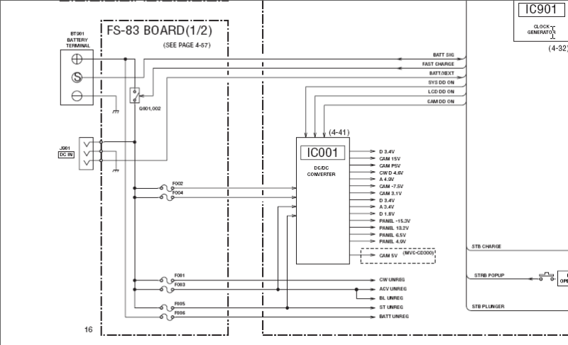 |
|