| Thank you, vtech.
PCAnalyze is too much for my objective. I'll reinstall all the components in the KS3A pcb, I'll leave the airbox with the fan to help removing heat, I'll place two wood blocks (one to the left, one to the right) beetwen the table and the tv to increment the air circulation under the tv. I was using wood blocks under the tv since the first time I mounted the new vertical ic and I discovered it overheated and burnt the board. It probably helped the LA7845N to be still alive after two years of work. If the first owner of the tv placed the wood blocks probably today there will not be burnt area in the pcb. |
|
| Glad to see that you have finally seen the light Actually, if you investigate further on the PCB material, you will notice a big difference. Migrating toward the cheaper phenolic types tend to scorch sooner than the epoxy type. And if you are really, really interested, one of the better thermal softwares in engineering is the PCanalyze |
|
| I might be honest: the vertical deflection ic in this KS3A works very hot, but this week I repaired the crt monitor
of my desktop pc, and I found the vertical ic gets hot after a few minutes. The monitor is LiteOn with chassis C1770NSL/T, the vertical deflection ic is the Philips TDA4863J, in this chassis the pcb doesn't have black or smoked area at top or bottom, it seems here nothing overheat, but after 15 minutes the very small radiator of the TDA4863J is as hot as LA7845N radiator, and all the component are ok in the monitor. So vtech is right: it's normal for this "modern" crt tv that the vertical ic runs hot. Probably the LA7845N burns the pcb (KS3A chassis) because there isn't enough space under the tv for air circulation. I don't know how much hours the KS3A worked everyday, but my low cost LiteOn crt monitor worked 2 hours a day from 2002 to 2011, but this monitor has an high swivel base that allow the air circulates on the bottom of the pcb, this could be the reason there aren't burnt area in the pcb. |
|
| Welcome in this post torbjorn, thank you very much for your precise and accurate information, but as I mentioned before I haven't a scope.
I know the scope is extremely indispensable when repairing tv, especially in this case. Several months ago, I saw in another forum a post written by professional technician, one of them saw there were a lot of ripple in the supply rails for the vertical ic. In fact, as I noted on their schematich, JVC, Mitsubishi and Panasonic when using the LA7845N they always put a capacitor of 1000uF in the positive rail and the same cap is in the negative rail, while Samsung always use less than an half the capacitance in uF with respect to the competitors. This might not solve the overheat problem but the better the filtration the longer last the circuit. But I don't know if the EAT transformer likes to surge such an increased capacitive load. I'll measure the current in the positive and negative rail. |
|
| If you use a scope and look at the waveform across the vertical coils or the feedback shunt R304, does everything look normal? No signs of clipping, no large DC component, not too much of horizontal frequency residues?
Check the positive and negative supplies to the vertical output to make sure that they have the correct voltage and are stable without ripple. Check the zener diodes DZ304, DZ305 and DZ306 to make sure that they have the correct breakdown voltage (disconnect one point in the series and then connect them one after another to a bench power supply with a series resistor of 10 kohm, adjust the supply so you have 10 volts drop over the series resistor and then measure the voltage across the zener diode). Try measuring the current from positive and negative supply (connect small resistors of, say, 0,22 ohms in series with the supplies and measure the voltage drop to determine the current. They should be almost equal and in the same range as the p-p current through the vertical coils (which you can measure as the voltage across R304). Look with a scope for signs of high frequency oscillations on the pins of the vertical output IC. |
|
| I need to know Rth(j-a), I asked this to Sanyo but the only e-mail contact in their website are referred to Sales Department, wrong place to ask techinical information.
I don't need to know "the ambient temperature of the heatsink", I need to know the Rth(j-a), it is the Junction Ambient Thermal Resistance, it's not a temperature. I can calculate Rth(j-a), but it's better if the producer add this info in the datasheet: Rth(j-a) = (Tj - Ta) / Pdmax = (150-25)/11 = 11.4°C/W (supposed and maybe wrong). To know what is the required dimension of the heatsink, because the original will destroy the ic in a year or two, and it will cook the board. I remember that Euras <<got the solution to the Samsung LA7845N overheat>>. "May be you need to see about designing a better vertical deflection circuit that will not run as hot?" No. I need to see a LA7845N that lasts in this Sams chassis. @minnie Thank you, I must specify there are no retrace line with the stock height value in service mode, they are visible only if I reduce the height. KS3A was (is) a crt tv chassis made by Samsung in 2000, a friend of mine was tired to spend a lot of money on repairing this cheap tv so he gave it to me (broken) as a gift. |
|
| Thought this is suppose to be an attempt to problem solving rather than a contest on who makes the better quality or reliable engineering?
I NEVER said anything about how reliable a brand is versus the other. Cheap stuff?? --of course there is cheaper stuff out there and have been for some time. Planned obsolescense is the game. Although you may not realize it, but perhaps you are comparing apples with oranges? What you bought years ago is not going to happen again in Consumer Electronics. Not only the materials used are cheaper, devices are pushed to their limits and so has the price has gone down. Perhaps it is not quite as bad on your part of the world but it IS reality. May be you need to see about designing a better vertical deflection circuit that will not run as hot? While you sound as if you may know about thermals, I am afraid you need to brush up on design criteria; Why would you need to know the ambient temperature of the heatsink?? --to prove that it will burn the board? Wonder why you did not get a response from Sanyo? Because it is NOT a needed criteria in design when dealing with a CONSUMEr product. Rth(j-c) is what is used to calculate the heatsink. This is not to say that there is no design flaws in products. http://www.rohm.com/products/discrete/transistor/tr-element/element05.html www.jaycar.com.au/images_uploaded/heatsink.pdf |
|
| I have no clue what a "KS3A" is but you need to replace the 100uf 35/50 volt pump up capacitor. This will get rid of your lines at the top. | |
| There is no problem in the video, except if I reduce the vertical height via service mode, because if I do this in
the top part of the screen there are three lines, one red, one blue, one green (retrace line?). The ic in this tellye never shutdown itself in case of overdriving. Samsung is the only one driving a LA7845N that reaches 65C degrees, the built in thermal protection circuit is ridiculous: it will never shutdown this ic because the LA is always below the maximum operating temperature, but at 65C degrees in a year or two the LA7845N will destroy itself! And the pcb around the LA is brown, completely cooked, in the bottom side it is very easy to break the wires. It is a low cost crt tv with low quality pcb, low quality cicuit design, it is designed to fail. In the datasheet there is Rth(j-c), it is the Junction Case Thermal Resistance, it has nothing to do with the Junction Ambient Thermal Resistance. I need Rth(j-a) to calculate how much degrees the heatsink will reach. Now I'll give you an example of extreme reliable engineering: My 1987 Blaupunkt crt tv works for 7 hours per day every day since 1987. Do you know how many semiconductors and Ics I changed in these 24 years? Zero. The only things I replaced in this chassis was the EAT transformer (when it was 15 years old), some year ago I changed the PTC and a bunch of resistors and electrolytic/ceramic capacitors. The Blaupunkt is a full digital controlled chassis, like the KS3A, the difference is: Blaupunkt used top quality components and knew how to drive semiconductors TO MAKE IT LAST, Samsung use low quality components and know how to drive semiconductors untill the end of the warranty. The operating +Vcc and -Vcc are as specs: +16.5V and -16.5V I saw another difference between Sams and Mitsu/Pana: the non inverting pin of the LA in the KS3A is driven by the Micom, in Mitsu/Pana chassis the non inverting pin is driven by the same LA through a circuit composed with 3 resistors, 1 diode and 1 zener. Could the Micom drive the LA in bad condition? I have no oscilloscope to prove this. |
|
| Exactly what do you mean by "overheat"? Does it cause any problem with the operation of the set/ distortion etc? There is a built-in circuit within the IC that will shut down the IC in case of overdriving? Is that what is happening?
The Rth(j-a) also known as thermal resistance is already shown in the datasheet. The size of the heatsink usually is more than enough for heat dissipation. Perhaps the operating VCC may be too high? 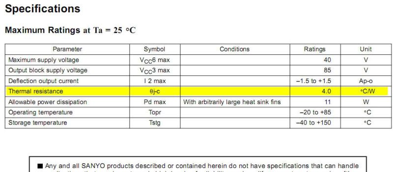 |
|