| View previous topic :: View next topic |
| Author |
Message |
SWECKER
Guest
|
 Posted: Sun Oct 05, 2014 10:14 pm Post subject: INSIGNIA 32" NS-LDVD32Q-10A Posted: Sun Oct 05, 2014 10:14 pm Post subject: INSIGNIA 32" NS-LDVD32Q-10A |
 |
|
| Everything works good except the cable connector is loose. I took the back off of the set and found the connector had come loose from the mounting and the center wire for the cable was not connected. I believe this is a simple solder fix, and would like to do it myself so I don't have to buy a complete main board (the tv was free), but not sure where the cable wire solders for the signal feed to the board. DVD player, and all controls, work great. Does anyone have a picture showing how this connector mounts? Or can describe how to fix? |
|
| Back to top |
|
 |
jts1957
Joined: 24 Nov 2008
Posts: 2476
Location: Far, Far Away
|
| Posted: Mon Oct 06, 2014 1:05 am Post subject: |
|
|
Usually those connectors 'come loose' from too much force being brought to bear.
Is there a lead remnant still in the mounting hole area of tuner that a wire could be soldered to? If so, Tack a wire to it and prove that tuner still works before deciding.
_________________
You're over there, I'm over here. |
|
| Back to top |
|
|
SWECKER
Guest
|
| Posted: Wed Oct 08, 2014 3:49 pm Post subject: No lead wire |
|
|
I looked and did not see a lead wire remnant but will look again. It almost looked like the center wire from the connector was soldered to the housing but really looks like someone else has already messed with the unit before it came to me so chances are they may have broken the remnant wire off and I will need to re-establish that portion. Just need to know where it connects so I know where to look.
I am pretty savvy to fix this kind of stuff but its been many years since playing with one of these issues. Just hate to put too much into the set but HATE to just have it as an oversized DVD Player laynig around too, or just throw in the trash  |
|
| Back to top |
|
|
jts1957
Joined: 24 Nov 2008
Posts: 2476
Location: Far, Far Away
|
| Posted: Wed Oct 08, 2014 4:55 pm Post subject: |
|
|
The usual is that the body of the 'F' connector is crimped, soldered or both to the tuner frames and the center pin is connected to the PC board.
Looks like it should go straight in though looking at Main board pictures. Probably looked SIMILAR to this with a smaller, straight center pin wire: 
Have you removed the tuner from the Main board and taken metal covers off both sides to inspect?
IF the PC Board of the tuner itself is intact, you'll have two possibilities: Attach and connect a replacement jack at the tuner itself or mount a connector somewhere near the tuner and run a coaxial cable between them. Either way it's a bit of work, hence trying to prove the tuner works before going to a lot of trouble.
_________________
You're over there, I'm over here. |
|
| Back to top |
|
|
swecker
Guest
|
| Posted: Sat Oct 25, 2014 6:24 pm Post subject: |
|
|
That is what it looks like but center "pin" is bent over like it was soldered to the frame where the connector mounts in. I know this is not right but I have not removed anything from the main board. Afraid if I did that I might as well just buy a new board for $120 and call it good. (Plug and play). But the challenge of making this work is too tempting and want to fix it. I will open the unit again and compare your suggestions to what I see going on and let you know.
Thanks |
|
| Back to top |
|
|
jts1957
Joined: 24 Nov 2008
Posts: 2476
Location: Far, Far Away
|
| Posted: Sat Oct 25, 2014 8:27 pm Post subject: |
|
|
http://www.shopjimmy.com/media/catalog/product/cache/1/image/f8f28dc4a19c21aeb55ee5774693fb5d/s/j/sjdtv32dgm59000.jpg
I DID say with a smaller, STRAIGHT center pin...
1) You will need to remove the tuner from the main board to get to the 'foil' side of the tuner's PC board.
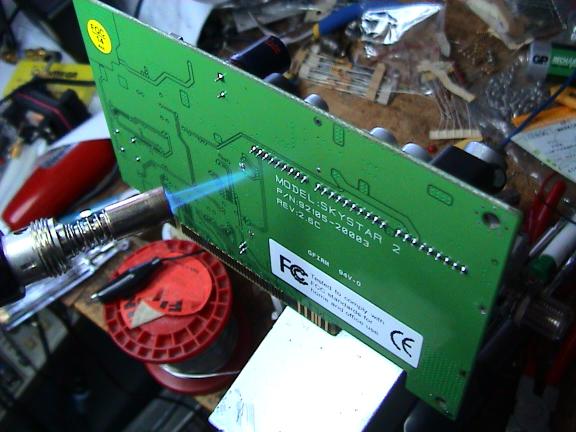
2) The board that the tuner is mounted upon is a 'double-sided' PC board. Do you have sufficient desoldering abilities and equipment to remove the tuner (at least ... 15 pins plus frame mounting at the corners) without irreparably damaging the board?
WRONG WAY TO REMOVE THE TUNER:
_________________
You're over there, I'm over here. |
|
| Back to top |
|
|
|
|
|

