| View previous topic :: View next topic |
| Author |
Message |
javelinpr
Joined: 04 Dec 2008
Posts: 9
Location: Puerto Rico
|
 Posted: Thu Dec 04, 2008 6:07 am Post subject: jvc th-m505 fixed a no power now no bass Posted: Thu Dec 04, 2008 6:07 am Post subject: jvc th-m505 fixed a no power now no bass |
 |
|
first of all im not the best as testing components. i dont have as much experience and i tend to need a guide on how to test everything and what to expect. just gotten a book that should help me on testing components.
With as little as i know im either very lucky or too smart. I have a Home theater system that i love to use. a couple months ago it puffed and it shut itself off. my wife was using it. a week or two ago i started testing on it and found 2 damaged caps(one was round and brown on the top and the other gave me continuity when tested). ordered it, mounted on the board and voila, it turned on. i also had sound on all channels except the subwoofer. so im stuck with no bass.
i dont have the experince to find whats wrong. i Do have the schematics for the unit and i also have the tools. using my little knowledge on this i thing that the problem could be and IC but i don know how to test those and i would prefer not to venture into changing one of them. Im willing to do whats necesarry to fix the thing. Should i post anything from the schematics?
so far ive tested the cables from the board to the SW and everything is good. all the fuses are good and i dont think i have more damaged caps. i dont really know where to keep testing and looking for the problem.
what my sig means is i paid for a year subscription at a schematic place and i will give away and use it as much as i can.
Thanks for the replys!!!
_________________
i can help and try to get you any schematic you need. I just ask for some help in exchange. If you are lucky i will have it and will be able to give it to you. |
|
| Back to top |
|
 |
vtech
Joined: 08 May 2006
Posts: 1264
Location: USA
|
| Posted: Thu Dec 04, 2008 6:37 am Post subject: |
|
|
Should not be difficult to determine as to why your sub/w is not working. Did the "blown caps" that restored the power were anywhere around the sub/w circuit or had nothing to do with that?
Not familiar with the specific unit but, what does it use for sub/w processing? is it a discrete output, an IC or part of one? Can you start with posting a block diagram? Provided that you have all of your relevant dc readings, if you have a scope & signal path, should be able to trace & see where you are loosing the signal? |
|
| Back to top |
|
|
javelinpr
Joined: 04 Dec 2008
Posts: 9
Location: Puerto Rico
|
| Posted: Thu Dec 04, 2008 3:12 pm Post subject: |
|
|
| vtech wrote: | Should not be difficult to determine as to why your sub/w is not working. Did the "blown caps" that restored the power were anywhere around the sub/w circuit or had nothing to do with that?
Not familiar with the specific unit but, what does it use for sub/w processing? is it a discrete output, an IC or part of one? Can you start with posting a block diagram? Provided that you have all of your relevant dc readings, if you have a scope & signal path, should be able to trace & see where you are loosing the signal? |
the blown caps are in the same board as the cable that powers the subwoofer. i think it is in the same circuit.
the subwoofer has everything inside it. the whole receiver in inside the enclosure of the sw. its a powered sw and it has all the outputs to all the speakers.
about tools i think i messed up, i dont have much tools(i think i wrote i had tools, i do just not a lot of tools to work on electronics). just everything needed to solder and desolder and a multimeter.
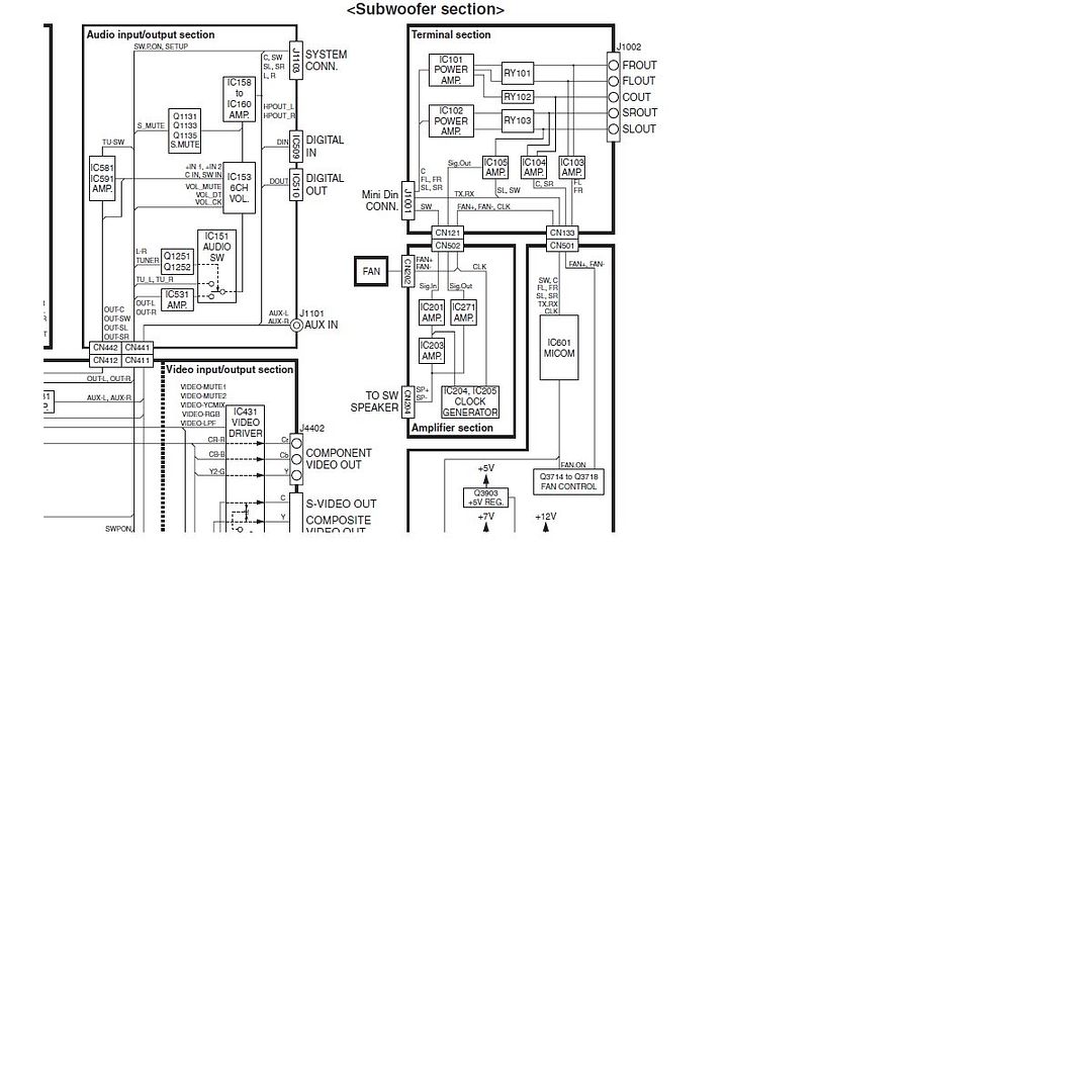
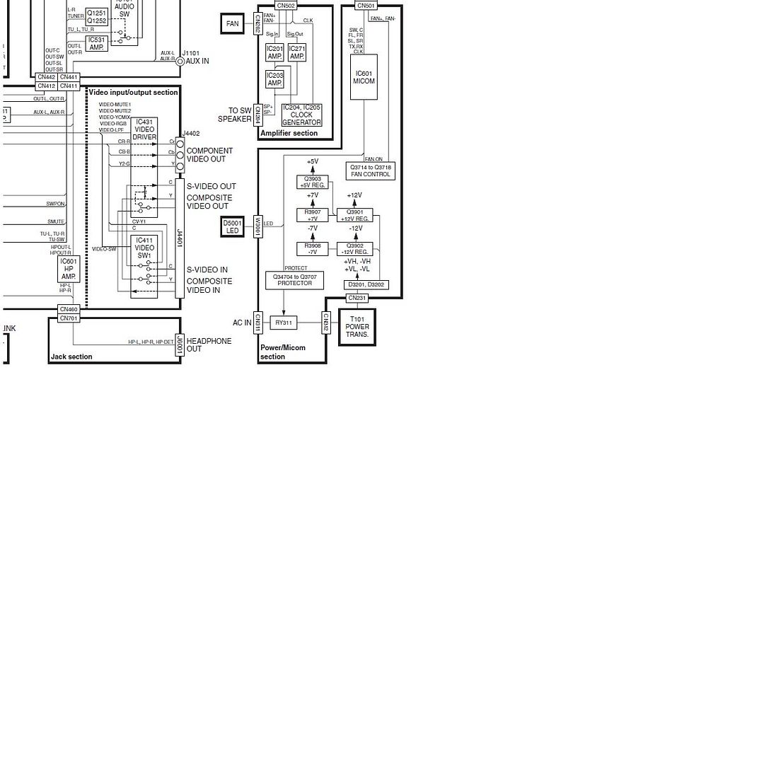
heres the block diagram. i will also provide a high res pic of the board im talking about.
_________________
i can help and try to get you any schematic you need. I just ask for some help in exchange. If you are lucky i will have it and will be able to give it to you. |
|
| Back to top |
|
|
javelinpr
Joined: 04 Dec 2008
Posts: 9
Location: Puerto Rico
|
| Posted: Thu Dec 04, 2008 3:14 pm Post subject: |
|
|
im working on the amplifier section board. forgot to add that.
_________________
i can help and try to get you any schematic you need. I just ask for some help in exchange. If you are lucky i will have it and will be able to give it to you. |
|
| Back to top |
|
|
vtech
Joined: 08 May 2006
Posts: 1264
Location: USA
|
| Posted: Thu Dec 04, 2008 4:43 pm Post subject: |
|
|
Do you hear a relay click inside the subwoofer? RY201. Appears to be a protection relay for the subwoofer.
At connector CN201(12 pin connector), is it intact & do you have all the needed voltages needed, (5v,-12v ,5v) etc?
I'd concentrate on measuring dc readings in sub/w section as much as possible and compare to schematic. |
|
| Back to top |
|
|
javelinpr
Joined: 04 Dec 2008
Posts: 9
Location: Puerto Rico
|
| Posted: Thu Dec 04, 2008 5:42 pm Post subject: |
|
|
my wife was using it at the time. she said she heard a puff sound inside the unit. it shouldnt been the cap as it was round and looked burned but didnt had openings in itself.
 how do i test the relay? how do i test the relay?
the 12 pin connector looks good, yes it has 5v 12v and -12v
please dont assume i very qualified on this, i just know the very basics. BUT im willing to put the time and effort to learn this. please if you are going to explain something go into details 
ive also seen the unit fan not working. it was a problem at first when i took it to a local shop. they "fixed" it but they didnt. they unit was working and when hot it would turn off by itself. protecting itself. fan would never go on. i think knowing this may be very important. but as soon as its working ill search and test to fix the fan.
_________________
i can help and try to get you any schematic you need. I just ask for some help in exchange. If you are lucky i will have it and will be able to give it to you. |
|
| Back to top |
|
|
Justmanuals
Joined: 21 Aug 2004
Posts: 1948
|
|
| Back to top |
|
|
javelinpr
Joined: 04 Dec 2008
Posts: 9
Location: Puerto Rico
|
| Posted: Thu Dec 04, 2008 6:25 pm Post subject: |
|
|
so ive tested the relay. apparently is good.
its giving me infinite on the open part of the relay and in the control pins is giving me 282 ohm when measuring on the 2000 scale of the meter.
ill proceed to testing the resistors on the sw side.
how can i test the ic 201 and 203 that are in charge of the sw?
_________________
i can help and try to get you any schematic you need. I just ask for some help in exchange. If you are lucky i will have it and will be able to give it to you. |
|
| Back to top |
|
|
vtech
Joined: 08 May 2006
Posts: 1264
Location: USA
|
| Posted: Thu Dec 04, 2008 9:29 pm Post subject: |
|
|
No need to test the relay. What I asked was if it is making a clicking sound indicating that it is activated or not. Also, What were exactly the caps that you replaced? reference numbers?
btw, happened to find a schematic in the archive |
|
| Back to top |
|
|
javelinpr
Joined: 04 Dec 2008
Posts: 9
Location: Puerto Rico
|
| Posted: Thu Dec 04, 2008 10:32 pm Post subject: |
|
|
i have the full schematics with the whole block diagrams, printed circuit boards and everything. If you need to take a look at those ill be more than happy to send em to you.
i replaced caps: c2901 and c2910 in the amplifier board.
by checking the fan tracings in the diagram i found its controller is at other board. so once i have this bass issue fixed(hopefully) ill work on the other board.
i will try to trace before and after the caps removed.
about the relay, everytime i turn the system it does a LOUD click. Has always done it.
_________________
i can help and try to get you any schematic you need. I just ask for some help in exchange. If you are lucky i will have it and will be able to give it to you. |
|
| Back to top |
|
|
|
|
|

