| View previous topic :: View next topic |
| Author |
Message |
i.robot
Guest
|
 Posted: Tue Sep 07, 2010 10:00 am Post subject: Yamaha RX-V1700 Posted: Tue Sep 07, 2010 10:00 am Post subject: Yamaha RX-V1700 |
 |
|
Hi All
I have an RX-V1700 that powers up with a display where only several pixels are illuminated.
It also shuts down in protect mode. The PRV signal line is at 0V. (This is puzzling since all supply voltages are up to specs).
It stays powered on in diag mode.
What I notice is when left on for several minutes, one of the two FL driver IC's gets pretty toasty to the touch.
Does anyone have any ideas if the display is at fault -or- the driver IC?
The protect mode error I believe is a separate problem. The PRV line doesn't seem to monitor any of the FL display voltages, although some of these voltages are not quite up to what the schematic says.
And for the guys at Just Manuals, I already have the schematic so don't bother trying to sell me.
Thanks a bunch,
Mike |
|
| Back to top |
|
 |
Reply
Guest
|
| Posted: Sun Feb 27, 2011 1:53 am Post subject: RX-V1700 |
|
|
Replaced FL driver IC (the one that gets toasty).
That problem is now fixed, but unit still has a PS (PS1) PRT fault.
Totally stumped. All voltages monitored by PS1 PRT are good. Checked and rechecked every component related to the monitoring circuit.
Unit works OK if I manually apply ~ 1.4VDC to PS1 PRT. |
|
| Back to top |
|
|
vtech
Joined: 08 May 2006
Posts: 1264
Location: USA
|
| Posted: Sun Feb 27, 2011 4:31 am Post subject: |
|
|
| You meant unit works ok if you apply ~1.4 v to PRV at supply section1? |
|
| Back to top |
|
|
irobot
Joined: 13 Mar 2009
Posts: 49
|
| Posted: Mon Feb 28, 2011 7:19 am Post subject: RX-V1700 |
|
|
Thanks for the reply!
Correct. ( PRV is displayed as PS1 and PRVS is PS2 in the diag mode
menu )
Discovered another issue. There is no video present at the MONITOR output.
Given the problems I'm having leads me to believe maybe someone had this thing open that didn't know what they were doing.
I found some defective diodes and transistors on one of the video input boards also.
I'll continue to fix whatever else I find, in the meantime any suggestions are appreciated. |
|
| Back to top |
|
|
vtech
Joined: 08 May 2006
Posts: 1264
Location: USA
|
| Posted: Tue Mar 01, 2011 3:35 am Post subject: |
|
|
Mike,
During the days that I was involved in consumer electronics and specifically Yamaha, I remember that regardless of the model, display related problems almost always pointed to some sort of a surge related damage;
You'd repair a portion only to come across" this-that and the other issues" and certainly sounds like what you have here?
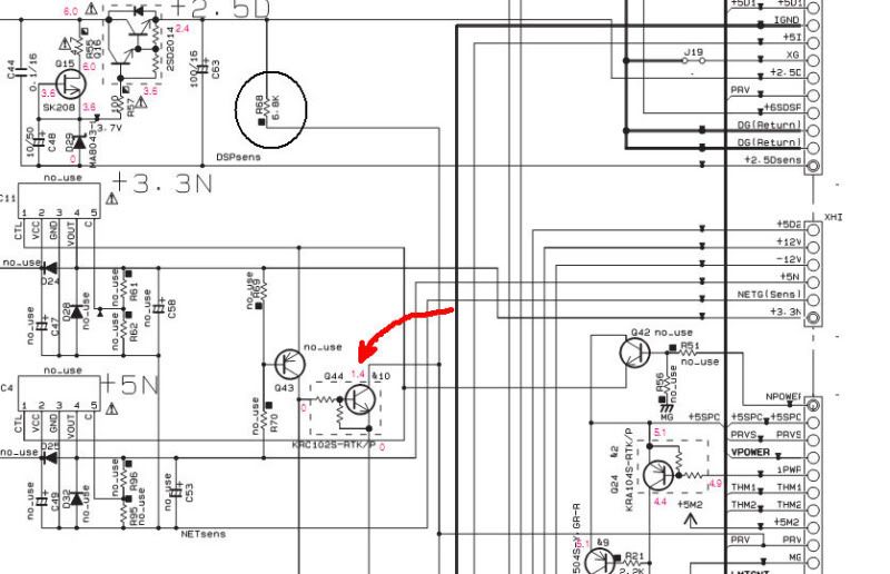
As far as the ~1.4V, if you follow the prv line back to the supply, you'll see that it is in fact labeled to be at 1.4v. It is sourced from the DSP2.5V thru R68... is the 2.5V running?... sound like you may have your hands full?
 |
|
| Back to top |
|
|
irobot
Joined: 13 Mar 2009
Posts: 49
|
| Posted: Tue Mar 08, 2011 6:40 am Post subject: RX-V1700 |
|
|
Hi
Thanks again for the reply and diagram.
I will check that area more carefully, especially R68.
(It looks like that 2.5D supply feeds a regulator that supplies 1.2V for the DSP. I don't think I tested any of the DSP functions but I'm sure I checked for ~1.2V at one time or another)
I'll post on what I find!
Thanks,
Mike |
|
| Back to top |
|
|
irobot
Joined: 13 Mar 2009
Posts: 49
|
| Posted: Wed Mar 09, 2011 11:15 pm Post subject: RX-V1700 |
|
|
The 2.5D supply is fine. Q44, Q23, R68 look good also. I may replace these anyhow.
An interesting observation - The XMPWR signal alternates between 0 and +5V, no matter what input is selected at the front panel.
Obviously, this causes the +5BUS supply to drop up and down. (+5BUS supplies power to the XM antenna jack)
But, in turn, this causes slight fluctuations at the cathode of D5309, which is tied to PRV, pin 5 of W5301. (This connector pin is not labeled on the schematic, I have no idea why. Hence it took a while to figure this also could be where the problem is. ) |
|
| Back to top |
|
|
|
|
|

