| View previous topic :: View next topic |
| Author |
Message |
Mikezore
Guest
|
 Posted: Sat Jun 30, 2012 7:05 pm Post subject: Dell M993s CRT Flyback Pinout Posted: Sat Jun 30, 2012 7:05 pm Post subject: Dell M993s CRT Flyback Pinout |
 |
|
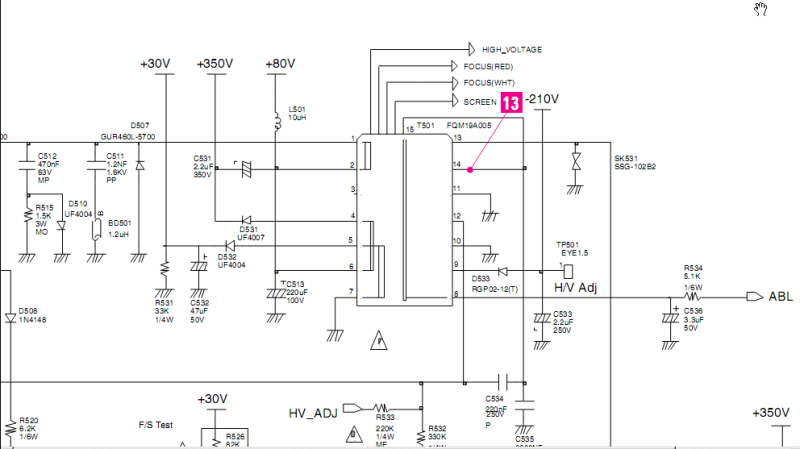
Hello, I have an old Dell m993s crt monitor that I have removed the FBT from to use for a little experiment of mine. I thought I would be able to just punch the id number in and find a pinout or datasheet, but alas, I cant find anyhting. I have found a rather generic trial and error method for identifying the primary and HV secondary coils but my dvom readings do not match what I have read. Can anyone help me in regards to this? I would like to have at least a basic pinout diagram identifying the various coils. The FBT part number is: FQM19A005. Rev .1 Monitor is a Samsung. Any help would be greatly appreciated.
Mike |
|
| Back to top |
|
 |
vtech
Joined: 08 May 2006
Posts: 1264
Location: USA
|
| Posted: Sat Jun 30, 2012 7:48 pm Post subject: |
|
|
Google "LEO PROJECT 11 Schematic" and You'll find your flyback 
 |
|
| Back to top |
|
|
Mikezore
Guest
|
| Posted: Sat Jun 30, 2012 10:02 pm Post subject: |
|
|
Much appreciated! But now my problem is I cannot make heads or tails of the connections. First they're are only 14 pins. I cannot find a 15th. Secondly it doesnt show a connection to the HV output. When I apply voltage to the various pins trying to figure out which is the ground for the HV coil, the only one that passes voltage thru to the HV output is pin 8. I am using a 19.5 volt source. With source applied to pin 8 i read .6v at the HV output. Could you possible explain the reason im getting these results? I'm beggining to wonder if im not messing with a burnt out FBT..
Thanks,
Mike |
|
| Back to top |
|
|
vtech
Joined: 08 May 2006
Posts: 1264
Location: USA
|
| Posted: Sun Jul 01, 2012 5:09 am Post subject: |
|
|
There is always a possibility of a bad fly but you must have the polarity correct. Are you trying to make a high voltage arc? The extra pin could be the center (around the core) or may not even be there?
Here is a link that shows how to find the pins.
http://lifters.online.fr/lifters/labhvps/tht.htm |
|
| Back to top |
|
|
Mikezore
Guest
|
| Posted: Fri Jul 06, 2012 2:59 pm Post subject: |
|
|
| Yeah that was the instruction i was using to identify the pins originally. I dont have a 24v supply like was recomended so im using a 19.5. But when i apply voltage to any of the pins i cant get a reading higher than 0.6v at the HV ouput plug. I can get an ohm and voltage reading across the secondary coils shown on the diagram but i can get neither across the HV coil. I'm begining to think the HV coil may be open.. I can think of no other reason for my readings. Any input would be much appreciated. |
|
| Back to top |
|
|
vtech
Joined: 08 May 2006
Posts: 1264
Location: USA
|
| Posted: Sun Jul 08, 2012 4:18 am Post subject: |
|
|
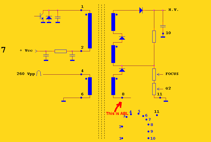
Ok, found a similar flyback diagram pinout. It is not the exact same one but it shows you how it is wired. In the world of CRT deflection there is always a pin from the flyback which is responsible for auto brightness limiting (called ABL). If you notice there are high voltage diodes in series within the flyback AND what is the average voltage for the brake over?
Around 24-26 volts (hence using the 24 volt for testing).
Take a closer look, the guy is using a 24 volt supply and reading about 6 volts (that is dropping about 18 volts and you are using 19.5 and dropping just about the same amount)
So, the other end of the wire is indeed pin 8.
 |
|
| Back to top |
|
|
Mikezore
Guest
|
| Posted: Thu Jul 12, 2012 5:01 pm Post subject: |
|
|
 Thankyou Thankyou for that clarification! I had no idea about that. Thankyou Thankyou for that clarification! I had no idea about that. |
|
| Back to top |
|
|
|
|
|

